120,182,268 visitors online since Thursday 30 September, 2004
Balance Bar Adjusting
The balance bar is an adjustable lever (usually a threaded rod), that pivots on a spherical bearing and uses two
separate master cylinders for the front and rear brakes. Most balance bars are part of a pedal assembly that
also provides a mounting for the master cylinders. When the balance bar is centered, it pushes equally on both
master cylinders creating equal pressure, given that the master cylinders are the same size bore. When adjusted
as far as possible toward one master cylinder it will push approximately twice as hard on that cylinder as the
other.
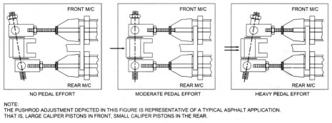
To set up the balance bar,
thread the master cylinder
push rods through their
respective clevises to obtain
the desired position.
Threading one push rod into
it's respective clevis means
threading the other one out
the same amount.
Sometimes this will lead to
a 'cocked' balance bar when
the pedal is in the relaxed
position, (Fig. 2 'no pedal
effort'). This is acceptable
as long as each master
cylinder push rod is
completely free of pressure
when the pedal is relaxed.
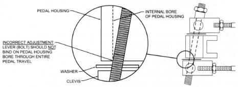
It is important that the operation of the
balance bar functions without
interference by over adjustment. This
can occur when a clevis jams against
the side of the pedal or the lever (bolt)
hits the pedal bore during any point of
pedal travel (Fig. 3).
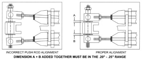
Lever movement should be unimpeded
throughout pedal travel. In the neutral
position, clevises should have between
.20" - .25" total clearance between the
side of the pedal. The large washers
between the pedal and clevis should
remain loose. Make sure that the master
cylinder push rods remain true in
relationship to the cylinder during the
entire pedal travel; push rods should
not be pushing master cylinder pistons
at an angle (Fig. 4).
NOTE:
In it's non-depressed position, the pedal
and balance bar should allow the push
rod of the master cylinders to fully
return. This can be checked by feeling
push rods for very slight movement, not
loose movement. Master cylinder
pistons should be against the retaining
snap ring (under boot).


.jpg "Gunson - Bolt Drilling Jig - Metric")